
TECHNICAL GUIDES
Understand Your Options.
Practical answers to common questions about selecting and specifying your products.
All Technical Resources →Thermocouples
Choosing a Thermocouple Type
The type identifies the pair of thermocouple alloys. Match the type to your operating temperature and process atmosphere.
- J
- Iron / Constantan. Used in vacuum, reducing or inert atmospheres; iron oxidation limits its life in oxidizing service.
- K
- Chromel / Alumel. Used in oxidizing or neutral atmospheres. Avoid sulfur exposure and certain low-oxygen conditions.
- T
- Copper / Constantan. Offers resistance to corrosion in moist atmospheres.
- E
- Chromel / Constantan. High thermoelectric output; listed for oxidizing or inert atmospheres.
- N
- Nicrosil / Nisil. Similar to Type K, with improved stability at high temperature.
- R, S & B
- Platinum / rhodium combinations for high-temperature service. Use suitable nonmetallic protection and ceramic insulation.
A type’s reference range is not the rating of a complete assembly. Wire gauge, sheath diameter, protection material and process conditions also matter; see the protected-thermocouple table.
Grounded or Remote Junction?
- Grounded
- The measuring junction is in electrical contact with the sheath. It responds more quickly than an otherwise comparable insulated junction.
- Remote (ungrounded)
- The measuring junction is electrically insulated from the sheath. Use this when electrical isolation is needed, such as where ground loops interfere with measurement. Response is slower than an otherwise comparable grounded junction.
- Dual-element junctions
- Two sensing elements can share a remote junction or use separate remote junctions. Choose the arrangement your application requires.
Single or Dual Sensing Elements
- Single (simplex)
- One sensing element in the assembly.
- Dual (duplex)
- Two separate sensing elements in the assembly. This is different from the number of leadwires used for each RTD element.
RTDs
Understanding the RTD Element
An RTD measures temperature through the change in electrical resistance of its sensing element. Specify the element material, nominal resistance and temperature coefficient (curve).
- Platinum
- 100, 500 and 1,000 Ω at 0°C, with 0.00385 or 0.003916 curves.
- Copper
- 10 Ω at 25°C, with a 0.00427 curve.
- Nickel
- 120 Ω at 0°C, with a 0.00672 curve.
Resistance and curve are separate parts of the specification. The element reference range does not establish the temperature rating of the complete probe and leadwire assembly.
RTD Lead Configurations
- 2 wire
- Leadwire resistance is included in the measurement; this arrangement does not compensate for it.
- 3 wire
- The third lead permits lead-resistance compensation. Accuracy depends on the lead resistances being matched.
- 4 wire
- The additional leads permit compensation without relying on matched lead resistances.
These descriptions refer to leads for one sensing element. Use the lead configuration required by your connected instrument.
RTD Accuracy Classes
For platinum elements with the 0.00385 curve, these classes describe the permissible deviation:
- Class A
- ±(0.15 + 0.002 × |T|) °C
- Class B
- ±(0.30 + 0.005 × |T|) °C
T is the temperature in °C; |T| is its absolute value. These are element tolerances, not a combined accuracy specification for the sensor, leads and measuring instrument.
Wire & Leads
Thermocouple & Extension Wire
Extension wire carries the thermocouple signal to the reference junction. Extension-wire temperature limits are separate from the thermocouple’s measuring range.
- J / JX conductor colors
- Positive white; negative red.
- K / KX conductor colors
- Positive yellow; negative red.
- T / TX conductor colors
- Positive blue; negative red.
- E / EX conductor colors
- Positive purple; negative red.
- N / NX conductor colors
- Positive orange; negative red.
These conductor colors help identify the thermocouple type and polarity. Connector case colors and overall jackets are separate. Use the correct thermocouple type and wire grade for the selected construction.
Wire Insulation & Temperature
The insulation reference separates continuous service from the maximum listed temperature. It also compares flexibility, abrasion, moisture and chemical resistance.
- PVC
- Continuous: −50 to 100°C (−58 to 212°F).
- FEP
- Continuous: −67 to 204°C (−90 to 400°F).
- PFA / TFE
- Continuous: −67 to 260°C (−90 to 500°F).
- Fiberglass
- Listed continuous limit: 482°C (900°F).
- High-temperature fiberglass
- Listed continuous limit: 760°C (1,400°F).
Use the reference for the specific insulation construction. A wire-insulation limit is not a rating for the complete sensor assembly.
Wire Gauge & Conductor Diameter
AWG identifies wire size. A larger AWG number means a smaller wire diameter. For stranded constructions, use the conductor construction listed with the option.
- 14 AWG
- 0.064″ conductor diameter
- 20 AWG
- 0.032″ conductor diameter
- 24 AWG
- 0.020″ conductor diameter
- 30 AWG
- 0.010″ conductor diameter
These diameters are for the conductor, not the outside diameter of its insulation or cable jacket. Use the tables below to check resistance per foot and temperature limits for protected thermocouples.
RTD Cable Conductors
Our PFA RTD cable uses 24 AWG nickel-plated conductors with a blue PFA outer jacket.
- 3 conductors
- One red and two white.
- 4 conductors
- Two red and two white.
- 6 conductors
- Three red and three white.
Cable conductor count and the lead configuration of an individual sensing element are different specifications.
Thermowells
Thermowell Shank Shapes
- Straight
- The outside diameter remains the same along the immersion length.
- Stepped
- The diameter is reduced near the tip to provide a quicker response.
- Tapered
- The diameter decreases gradually along the immersion length. Used in high-velocity applications.
Shape alone does not establish suitability for a process. NBS reviews the complete thermowell specification and application.
Thermowell Bore Diameter
The bore is the inside diameter that receives the sensor or thermometer stem.
- 0.260″ bore
- Designed to receive a ¼″ outside-diameter probe or thermometer stem.
- 0.385″ bore
- Designed to receive a ⅜″ outside-diameter probe or thermometer stem.
Bore diameter and insertion length are separate fit requirements. Use the measuring guide for the selected thermowell style.
Thermowell U & T Dimensions
- U — immersion
- Measured from the bottom of the process connection to the thermowell tip.
- T — lag extension
- An extension behind the process connection, used to provide clearance through insulation, walls or fittings.
Use the dimension arrows in this product’s measuring guide. The fixed connection length is shown separately from additional T lag.
Protection Tubes
Protection-Tube Material Reference
The material chart lists composition, recommended maximum temperatures, applications and limitations for metal and ceramic protection tubes.
- Metal tubes
- Compare the specific stainless grade or alloy, not just “stainless steel.” The application remarks include atmosphere and corrosion considerations.
- Ceramic tubes
- Use the ceramic material’s own application and temperature guidance. Metal-tube limits do not apply to ceramic constructions.
The chart is material reference data. The complete assembly and its suitability depend on the construction and process conditions.
Nominal Pipe Size vs. Actual Diameter
Nominal pipe size is a size designation; it is not the measured outside diameter. Outside diameter, wall thickness and inside diameter are separate dimensions.
- ⅛″ nominal pipe
- 0.405″ outside diameter
- ¼″ nominal pipe
- 0.540″ outside diameter
- ⅜″ nominal pipe
- 0.675″ outside diameter
- ½″ nominal pipe
- 0.840″ outside diameter
- ¾″ nominal pipe
- 1.050″ outside diameter
- 1″ nominal pipe
- 1.315″ outside diameter
For a given nominal pipe size, the schedule changes wall thickness and inside diameter. Check the matching schedule in the table.
Connections & Components
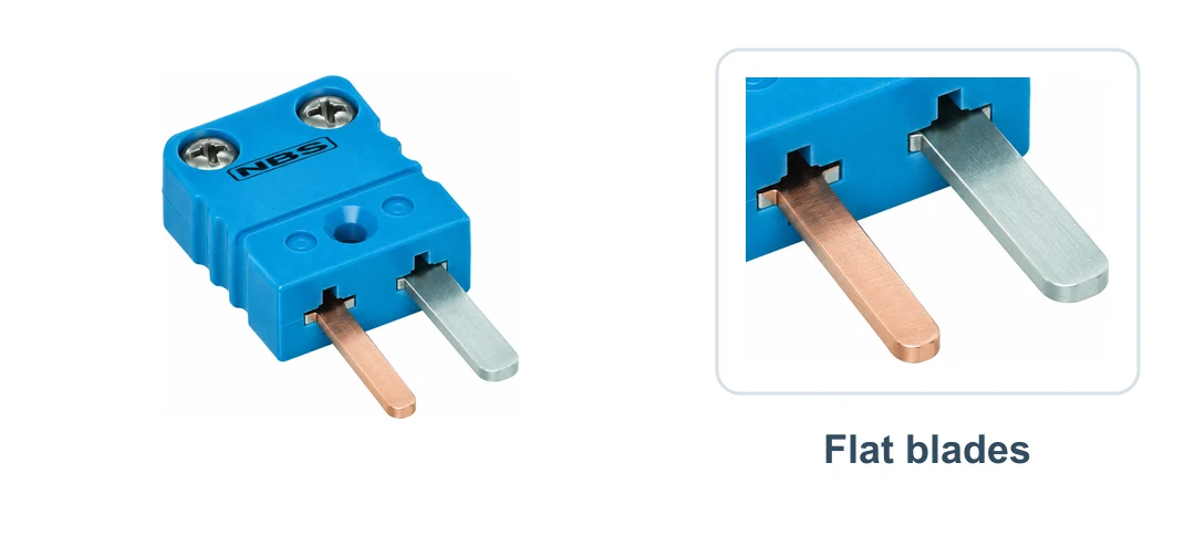
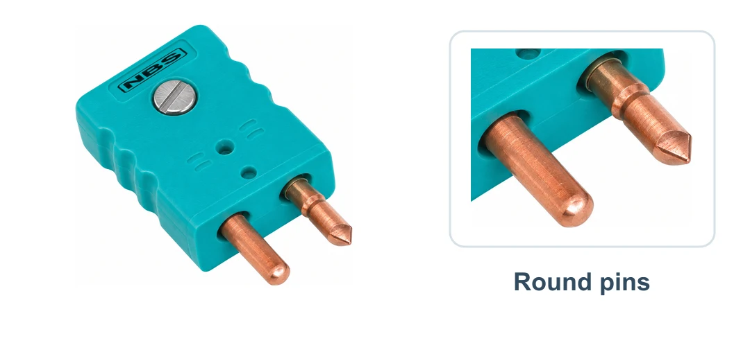
Miniature & Standard Connectors
Compression Fitting Specifications
Choose the mounting NPT thread and the tube outside diameter separately.
- Brass fitting
- Brass body with a brass ferrule.
- Stainless steel fitting
- Stainless steel body with a stainless steel ferrule.
- Readjustable stainless steel fitting
- Stainless steel body with a Teflon ferrule.
Choose the tube O.D. that matches the probe and the NPT thread required by the mounting connection.
Understanding NPT Connections
NPT means American National Standard taper pipe thread. A nominal pipe/thread size is not the measured outside diameter.
Follow the connection specified for the selected product. A tube connection, process connection and conduit connection can be different sizes.
Connection Heads & Enclosure References
Connection heads vary in material, cover style, terminals, tube connection and conduit connection. The enclosure sheets below explain the terminology.
The enclosure and hazardous-location sheets are historical references based on NEMA 250-1997 and NFPA 497M-1983. They do not establish a rating or approval for the head you select. Include any required rating in your quote notes for NBS to review.
Measurement & Terms
Temperature Units & Range
A temperature range has a lower and an upper limit. Use the same units when specifying the operating temperature and the required instrument range.
- Celsius to Fahrenheit
- °F = (°C × 9/5) + 32
- Fahrenheit to Celsius
- °C = (°F − 32) × 5/9
Fractions, Decimals & Millimeters
- ⅛″
- 0.125″ = 3.175 mm
- ¼″
- 0.250″ = 6.350 mm
- ⅜″
- 0.375″ = 9.525 mm
- ½″
- 0.500″ = 12.700 mm
- 1″
- 25.400 mm
Enter the units requested by the field. For A, B, C, U and T dimensions, follow the reference points on the selected product’s drawing.